



Integrated building blocks
Bring radio access, local core functions and the selected NTN service into one considered network plan.
5G NETWORK SOLUTIONS THAT EMPOWER YOUR BUSINESS AND SOLVES CRISIS COMMUNICATION

NETWORK ARCHITECTURE
Explore how radio access, the core network, connected devices and applications fit together. A clear view of the architecture helps turn operational needs into a practical deployment plan.
01 / EMERGENCY COMMUNICATION ARCHITECTURE
From the terminal in the field to the applications used by command teams, every layer has a role. This reference architecture brings deployable networks, transport links and emergency services into one clear view.

The services that support the mission.
The paths that carry information onward.
Field networks and command coordination.
DEPLOYED COMMUNICATION NETWORK
Broadband ad hoc links between compatible field nodes
WIDER NETWORK
National emergencyThe devices used by people and equipment.
Identify the response teams, the information they need and the applications that support their work.
Combine field infrastructure with suitable onward transport. The right mix depends on the site and the links available.
Plan terminals, local links and command-system integration together, so each part supports the same operation.
Conceptual emergency communication architecture. The transport options shown are alternatives or complementary paths; the final topology and interoperability depend on the selected deployment.
02 / EMERGENCY COMMAND ARCHITECTURE
A command platform connects the people making decisions with the information coming from the field. This layered view brings interfaces, operational applications, data and communication networks into one architecture.
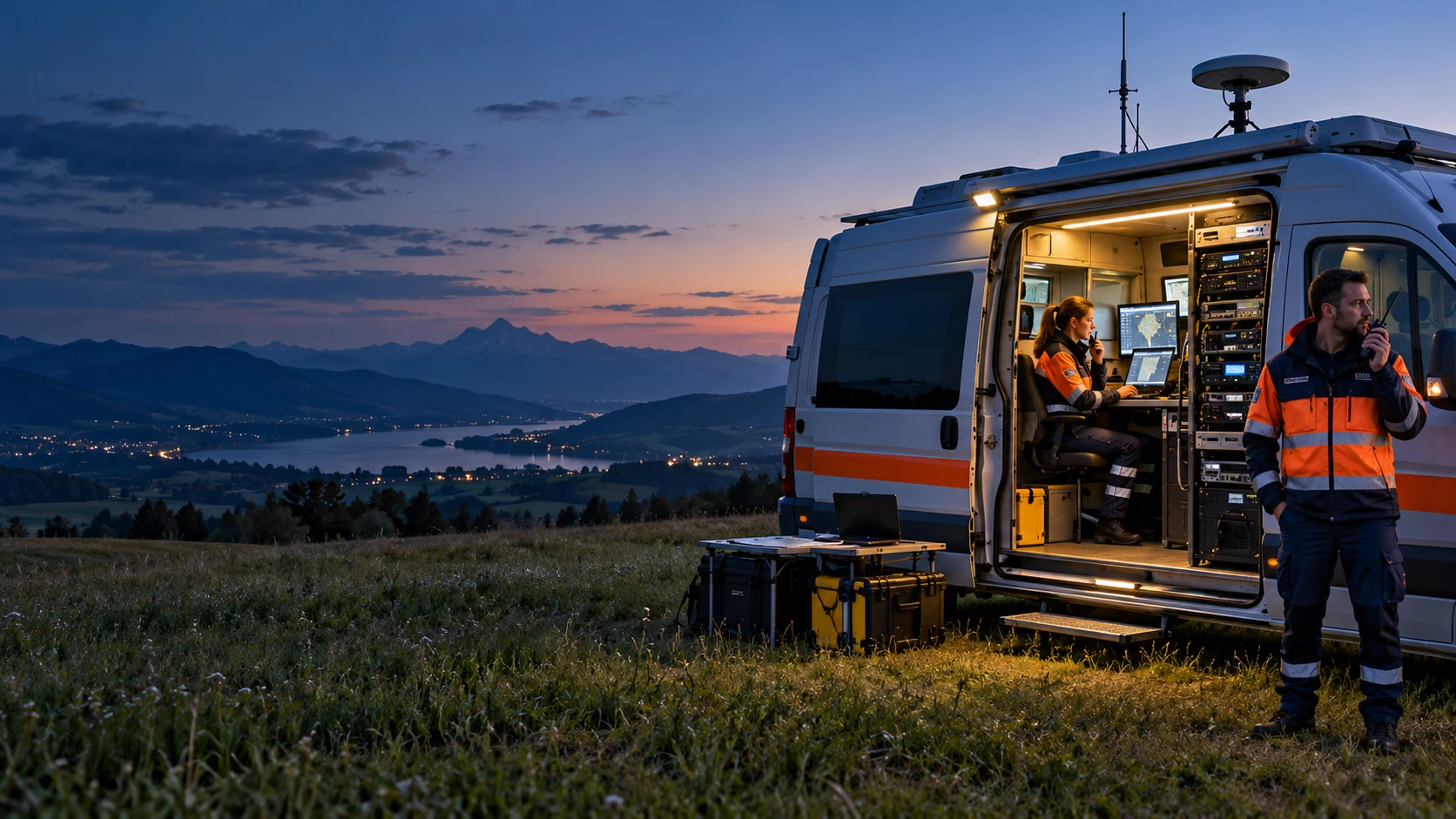
A shared operating picture across locations.
Tools for mapping, communication and video.
Governance, exchange and operational context.
Communication paths that connect the system.
Information and communication at the edge.
Command-centre, vehicle, mobile and handheld interfaces give different teams access to the information and coordination tools their roles require.
Mapping, communication and video tools depend on well-managed data, clear interfaces and an agreed path from field devices to operational applications.
Management and security span all layers, including access rights, integration ownership and the operation of the connected platform.
Functional command architecture. Features and integration points are selected for each deployment.
03 / EMERGENCY SECURITY ARCHITECTURE
Security is built from several connected mechanisms. Authentication establishes who can join; radio, transport and operational controls protect different parts of the communication path.

PRIMARY AUTHENTICATION · LOGICAL FUNCTION CHAIN
Transport protection and application-layer security are planned separately for the onward path. VLAN segmentation alone does not encrypt traffic.
The device, serving network and authentication functions establish the security context used for access and subsequent key derivation.
Radio protection, NAS protection and transport protection cover different scopes. A protected radio link is one part of the complete application path.
Equipment protection, permissions, monitoring and certificate management need clear configuration and operational ownership.
Simplified functional view. Security roles follow 3GPP TS 33.501 / ETSI. Mechanisms, algorithms and user-plane integrity depend on equipment capability, network policy and configuration.
04 / RESILIENT WIRELESS ARCHITECTURE
A resilient communication design considers what happens when a link becomes constrained or unavailable. Combining a local 5G network with an appropriate non-terrestrial connection can create additional options for field-to-command communication.
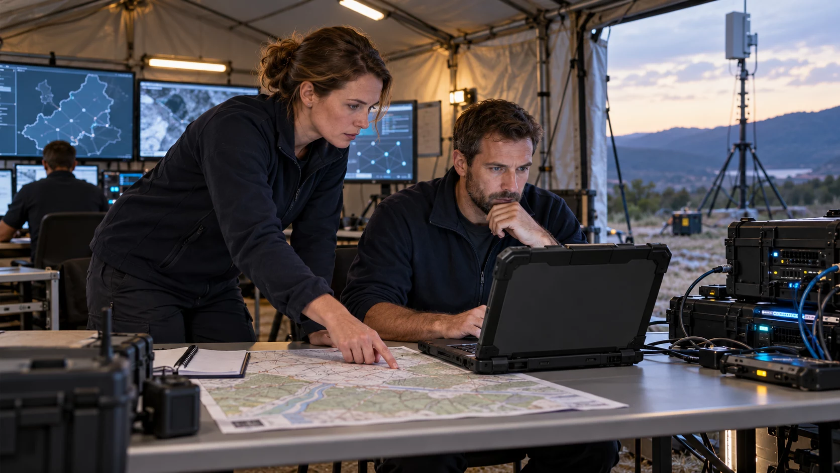
Coordination services · operational data · network management
One coordinated design, with terrestrial and non-terrestrial communication paths.
Satellite-based access or onward connectivity, according to the selected equipment and service.
Local radio coverage connecting compatible terminals, gateways and field applications.
DISTRIBUTED FIELD EQUIPMENT
Communication for authorised field users
Connect equipment and operational data
Video, sensors and local processing
Bring radio access, local core functions and the selected NTN service into one considered network plan.
Evaluate channel conditions, available capacity and routing policies when selecting or combining communication paths.
Plan interfaces between the field network, command applications and existing operational systems.
Select voice, video, data and edge-processing functions around the work of the response team.
Define power, antenna placement, service activation and the configuration needed before deployment.
Match radio bands, authorisations, terminals and satellite service support to the intended location.
Conceptual hybrid architecture. NTN denotes non-terrestrial networking; direct NTN access and satellite backhaul are different integration choices. Simultaneous operation, path switching and service continuity depend on the selected equipment, service and configuration.
05 / EMERGENCY DEPLOYMENT ARCHITECTURE
A deployable network connects the devices used by field teams to local radio equipment, onward transport and command applications. The architecture stays clear when each part has a defined role.
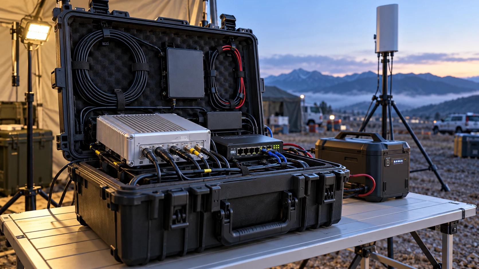
01 / FIELD ENDPOINTS
02 / LOCAL ACCESS
Transportable network equipment
Local connectivity at the operating site
On-site communication and coordination
03 / ONWARD CONNECTION
Selected satellite service
Compatible relay nodes
Where a suitable service is available
04 / COORDINATION
Operational applications and the teams coordinating the response
Bring compatible voice, video and data services into the same deployment architecture.
Choose equipment weight, dimensions, power and accessories for the way teams will carry and install the system.
Use a defined configuration and installation plan to make site deployment straightforward and repeatable.
Evaluate terrain, coverage, environmental exposure and the onward links available at the operating site.
Conceptual deployment view. Onward links are selected for the site and need not all operate together. Coverage, endurance and setup time depend on the equipment, power supply and installation.
06 / DISASTER RESPONSE ARCHITECTURE
Wildfire and geological-response operations may spread teams across several locations. This concept combines local access, inter-site relays and onward communication to link rescue teams, a forward command post and remote coordination.
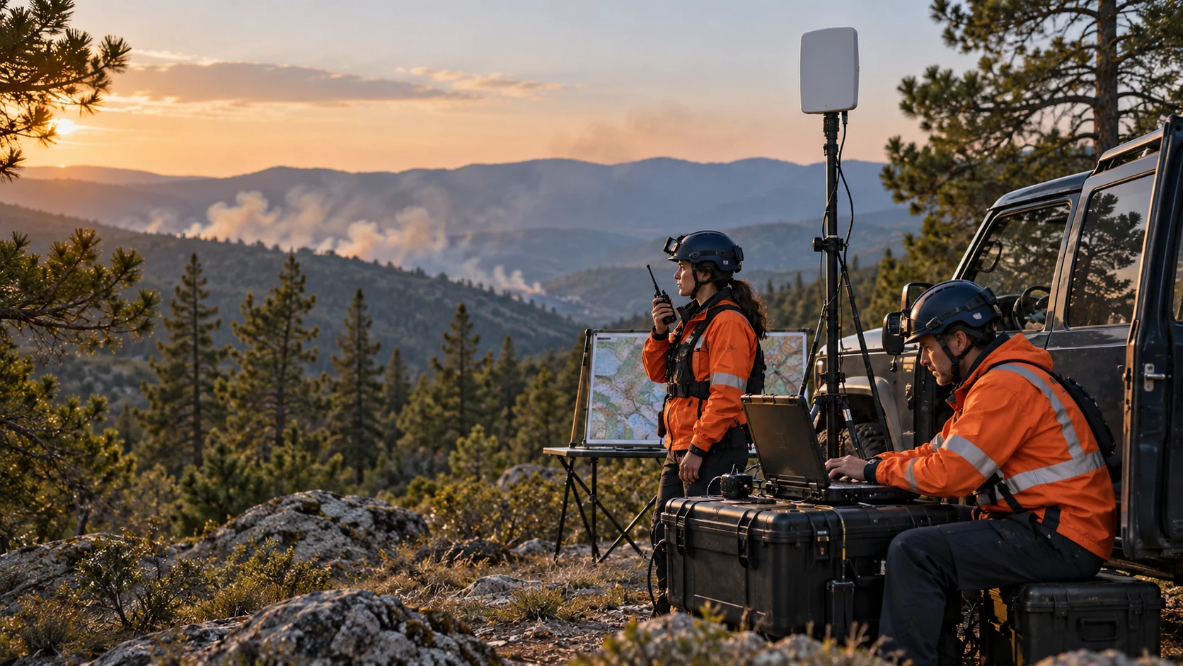
An onward path for appropriately equipped field sites and command systems.
Connect distributed operating points using compatible nodes and a topology planned for the terrain.
Vehicle-mounted station, field team, cameras and compatible airborne observation.
Vehicle-mounted network equipment, handheld communication and local dispatch.
Portable station, authorised handheld terminals and field applications.
Share the audio, video, mapping and operational information needed to coordinate distributed teams.
Provide suitable access around each working area, with terminals and applications selected for the task.
Plan relay-node spacing, line of sight and the information that needs to move between rescue sites and forward command.
Use available onward connectivity, including a suitable satellite service where selected, to connect the wider coordination system.
Conceptual multi-site architecture. Satellite links require suitable terminals and service; radio access and ad hoc relays are selected for the terrain, equipment compatibility and required traffic.
07 / URBAN FIREFIGHTING ARCHITECTURE
Urban incidents bring teams into very different radio environments. This concept connects airborne observation, indoor teams, surface operations and underground response through an incident command vehicle and a remote command centre.
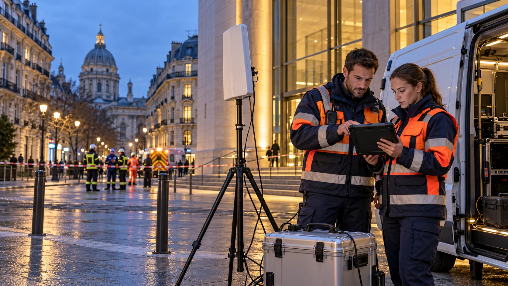
Airborne observation and compatible communication terminals
5G accessTeams and devices working inside buildings
5G accessVehicles, staging areas and street-level teams
Wireless relayForward teams supported by suitable relay nodes
Wireless relayBring field information, local communication and onward links together at the scene.
Satellite or another suitable connection to the remote command system
Combine the information needed to coordinate teams across the incident.
Plan radio access and relay placement separately for air, indoor, surface and underground operations.
Connect authorised devices and field applications to the incident command point using compatible links.
Define the onward connection and the audio, video, mapping and data services needed by remote command.
Conceptual urban-response architecture. Radio access and relay suitability are evaluated for each environment; this view does not assume that one radio link covers every building or underground space.

FROM ARCHITECTURE TO APPLICATION
Start with your site, your devices and the information your teams need to share. Together, we can map the network roles, integration points and deployment priorities.